Independent engineering project
Compact F/4
Industrial Imaging Objective
From an imaging task to an integrated optical and mechanical design: developing the lens system, packaging it, and using simulation to find and resolve an integration problem.
- My role
- Independent designer
- Scope
- Optics + mechanics
- Validation
- Simulation
01 / The task
Design the system,
not just the lens.
I undertook this independent hobby project to practice developing an optomechanical imaging system from initial requirements through optical design, mechanical packaging, and virtual evaluation.
The imaging task called for a compact, fixed-focus objective for a 5 MP machine-vision sensor. I used the sensor sampling and finite-distance object field to guide the optical targets, then treated image quality and mechanical compatibility as linked design problems.
- Balance image quality across the field at F/4.
- Keep nominal distortion below a selected 0.5% design limit.
- Evaluate sensitivity to manufacturing and assembly errors.
- Locate and retain the optics while limiting barrel-induced clipping.
02 / Optical development
The corner field
sets the challenge.
I developed the optical design in Zemax OpticStudio, progressing from first-order sizing to aberration correction and performance evaluation. Aspheric correction provided additional freedom to address the limiting corner field while retaining a compact architecture.
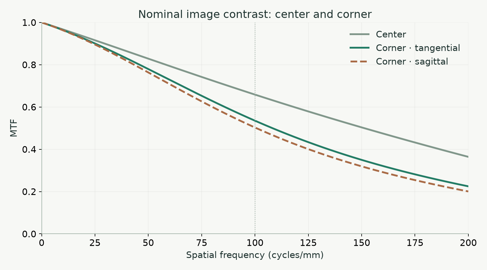
I evaluated the design using MTF, geometric spot size, and distortion together. A fresh nominal analysis gives a corner RMS spot radius of approximately 3.76 µm. The exported visible-wavelength distortion curves remain below the selected 0.5% limit.
03 / Mechanical integration
A seat can become
an optical obstacle.
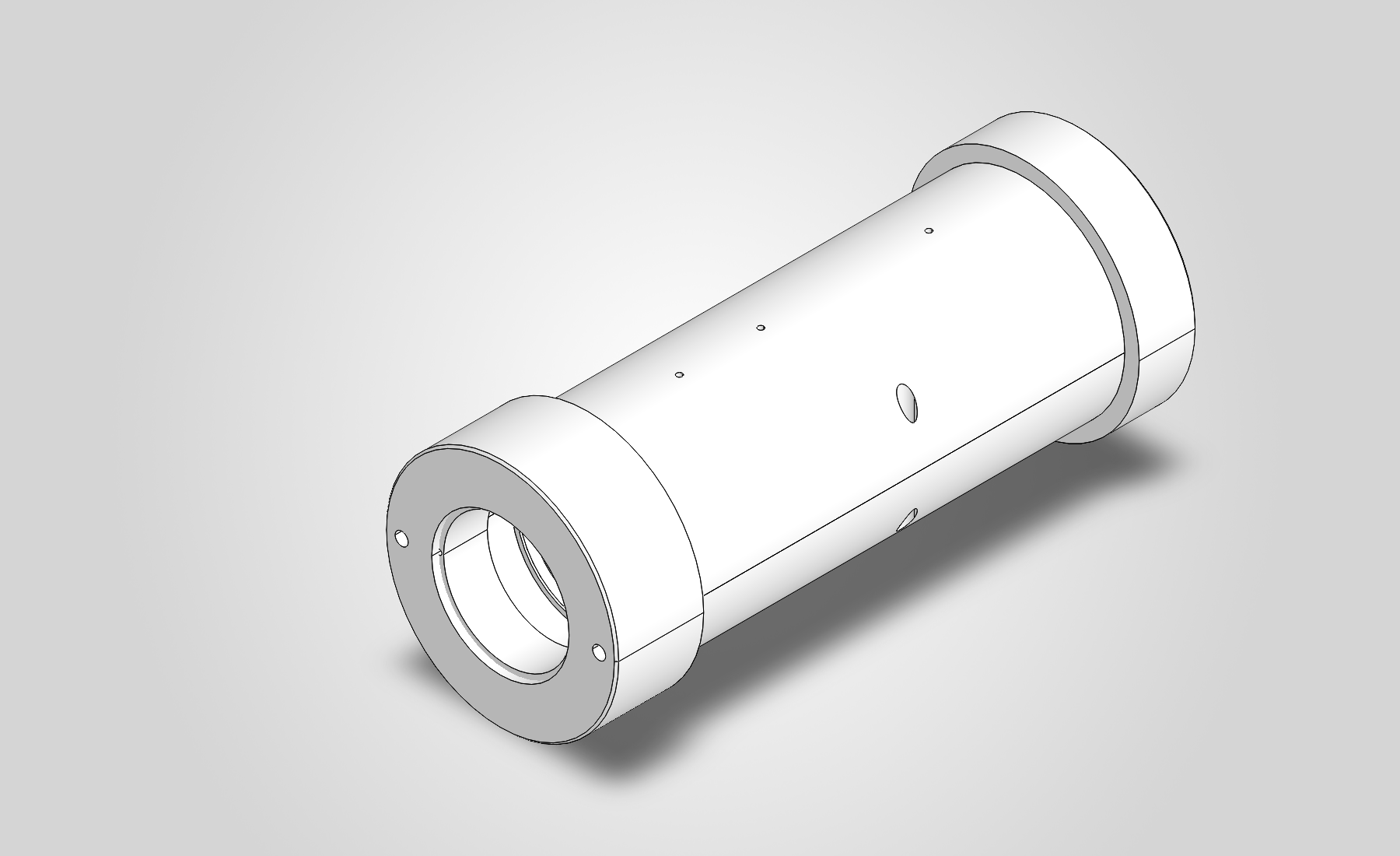
I developed the mechanical barrel in SolidWorks and integrated its CAD geometry into Zemax’s non-sequential environment. Lens location, spacing, and retention had to support the optical design while allowing the intended ray bundles to reach the sensor.
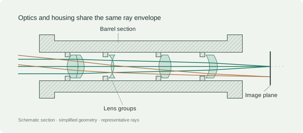
The initial barrel reduced direct transmission at the corner field. By isolating mechanical components in the simulation, I identified a rear lens locating seat as a major clipping contributor and revised its geometry.
Compare optical-only and packaged models, then isolate the obstructing component.
Revise the seat to clear the ray envelope while preserving its locating function.
Check the revised component and the complete barrel in the optical model.
The project validation summary reports that full-barrel corner-field transmission improved from approximately 95.5% to 98.52%. The isolated revised seat transmitted all direct rays in its reported test. The remaining full-assembly loss shows why checking one corrected part is only one step in the integration process.
04 / Validation chain
Four states.
Four different questions.
I separated nominal imaging, tolerance sensitivity, optical-model conversion, and mechanical integration so that each comparison answered a specific engineering question.
| State | Engineering question | Selected result |
|---|---|---|
| 1 · Nominal optics | Does the unperturbed design meet the selected imaging targets? | Corner MTF above 0.50 in both orientations at 100 cycles/mm; RMS spot radius 3.76 µm. |
| 2 · Toleranced optics | How sensitive is performance to modeled fabrication and assembly errors? | Mean corner MTF 0.461; 83.8% of 500 trials at or above the selected 0.4 threshold. |
| 3 · Optical-only NSC | Does the converted model establish a usable direct-ray baseline? | Reported direct throughput 100%; NSC RMS spot radius 2.447 µm. |
| 4 · Full optomechanical NSC | What changes when the barrel interacts with the rays? | Reported direct throughput 98.52%; NSC RMS spot radius 2.438 µm. |
Sequential and NSC spot radii use different sampling and reference methods. The small RMS reduction after adding the barrel is not evidence of an optical improvement. Tolerance yield describes the modeled study, rather than measured manufacturing yield; the historical tolerance criterion and fresh FFT curves also use different analysis settings.
Beyond direct transmission
The study also explored coating throughput, detector-reaching ghosts, a provisional barrel-scatter model, and out-of-field illumination. An off-axis challenge exposed direct optical spillover, illustrating that good nominal imaging and low nominal scatter do not by themselves establish out-of-field rejection.
05 / Lessons
Close the loop
between disciplines.
The most useful part of this project was connecting a ray-trace result to a mechanical cause, making a targeted change, and returning to the full-system model to evaluate it.
The tolerance study also showed that nominal image quality alone is not a sufficient design endpoint: the corner field remained sensitive to modeled errors even after the barrel clipping was reduced.
What comes next
Moving this study toward a physical prototype would require thermal assessment, manufacturing and inspection planning, preload and contact-stress checks, sensor-package integration, and experimental validation. Those steps remain future work.
Get in touch
Let’s work together.
For hiring opportunities, project collaborations, or business inquiries, get in touch.